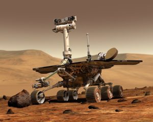
I was doing my daily trawl of the internet a few days ago looking at the latest news in artificial intelligence (especially computer vision) and an image caught my eye. The image was of one of the Mars Exploration Rovers (MER) that landed on the Red Planet in 2004. Upon seeing the image I thought to myself: “Heck, those rovers must surely have used computer vision up there!?” So, I spent the day looking into this and, sure as can be, not only was computer vision used by these rovers, it in fact played an integral part in their missions.
In this post, then, I’m going to present to you how, where, and when computer vision was used by those MERs. It’s been a fascinating few days for me researching into this and I’m certain you’ll find this an interesting read also. I won’t go into too much detail here but I’ll give you enough to come to appreciate just how neat and important computer vision can be.
If you would like to read more about this topic, a good place to start is “Computer Vision on Mars” (Matthies, Larry, et al. International Journal of Computer Vision 75.1, 2007: 67-92.), which is an academic paper published by NASA in 2007. You can also follow any additional referenced publications there. All images in this post, unless otherwise stated, were taken from this paper.
Background Information
In 2003, NASA launched two rovers into space with the intention of landing them on Mars to study rocks and soils for traces of past water activity. MER followed upon three other rover-based missions: the two Viking missions of 1975 and 1976 and the Mars Pathfinder mission of 1997.
Due to constraints in processing power and memory capacity no image processing was performed by the Viking rovers. They only took pictures with their on-board cameras to be sent back to Earth.
The Sojourner (the name of the Mars Pathfinder rover), on the other hand, performed computer vision in one way only. It used stereoscopic vision to provide scientists detailed maps of the terrain around the rover for operators on Earth to use in planning movement trajectories. Stereoscopic vision provides visual information from two viewing angles a short distance apart just like our eyes do. This kind of vision is important because two views of the same scene allows for the extraction of 3D data (i.e. depth data). See this OpenCV tutorial on extracting depth maps from stereo images for more information on this.
The MER Rovers
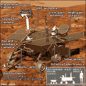
The MER rovers, Spirit and Opportunity as they were named, were identical. Both had a 20 MHz processor, 128 MB of RAM, and 256 MB of flash memory. Not much to work with there, as you can see! Phones nowadays are about 1000 times more powerful.
The rovers also had a monocular descent camera facing directly down and three sets of stereo camera pairs: one pair each at the front and back of the rovers (called hazard cameras, or “hazcams” for short) and a pair of cameras (called navigation cameras, or “navcams” for short) on a mast 1.3m (4.3 feet) above the ground. All these cameras took 1024 x 1024 greyscale photos.
But wait, those colour photos we’ve seen so many times from these missions were fake, then? Nope! Cleverly, each of the stereoscopic camera lenses also had a wheel of 8 filters that could be rotated. Consecutive images could be taken with a different filter (e.g. infrared, ultra-violet, etc.) and colour extracted from a combination of these. Colour extraction was only done on Earth, however. All computer vision processing on Mars was therefore performed in greyscale. Fascinating, isn’t it?
The Importance of Computer Vision in Space
If you’ve been around computer vision for a while you’ll know that for things such as autonomous vehicles, vision solutions are not necessarily the most efficient. For example, lidar (Light Detection And Ranging – a technique similar to sonar for constructing 3D representations of scenes by emitting pulsating laser light and then measuring reflections of it) can give you 3D obstacle avoidance/detection information much more easily and quickly. So, why did NASA choose to use computer vision (and so much of it, as I’ll be presenting to you below) instead of other solutions? Because laser equipment is fragile and it may not have withstood the harsh conditions of Mars. So, digital cameras were chosen instead.
Computer Vision on Mars
We now have information on the background of the mission and the technical hardware relevant to us so let’s move to the business side of things: computer vision.
The first thing I will talk about is the importance of autonomy in space exploration. Due to communication latency and bandwidth limitations, it is advantageous to minimise human intervention by allowing vehicles or spacecraft to make decisions on their own. The Sojourner had minimal autonomy and only ended up travelling approximately 100 metres (328 feet) during it’s entire mission (which lasted a good few months). NASA wanted the MER rovers to travel on average that much every day, so they put a lot of time and research into autonomy to help them reach this target.
In this respect, the result was that they used computer vision for autonomy on Mars in 3 ways:
- Descent motion estimation
- Obstacle detection for navigation
- Visual odometry
I will talk about each of these below. As mentioned in the introduction, I won’t go into great detail here but I’ll give you enough to satisfy that inner nerd in you 😛
1. Descent Image Motion Estimation System
Two years before the launch of the rocket that was to take the rovers to Mars, scientists realised that their estimates of near-surface wind velocities of the planet were too low. This could have proven catastrophic because severe horizontal winds could have caused irreparable damage upon an ill-judged landing of the rover. Spirit and Opportunity had horizontal impulse rockets that could be used to reduce horizontal velocity upon descent but no system to detect actual horizontal speed of the rovers.
Since a regular horizontal velocity sensor could not be installed due to cost and time constraints, it was decided to turn to computer vision for assistance! A monocular camera was attached to the base of the rover that would take pictures of the surface of the planet as the rovers were descending onto it. These pictures would be analysed in-flight to provide estimates of horizontal speeds in order to trigger the impulse rockets, if necessary.
The computer vision system for motion estimation worked by tracking a single feature (features are small “interesting” or “stand-out” patches in images). The feature was located in photos taken by the rovers and then the position of these patches was tracked between consecutive images.
Coupled with this feature tracking information and measurements from the angular velocity and vertical velocity sensors (that were already installed for the purpose of on-surface navigation), the entire velocity vector (i.e. information about the magnitude and direction of the rover’s speed) was able to be calculated.
The feature tracking algorithm, called the Descent Image Motion Estimation System (DIMES) consisted of 7 steps as summarised by the following image:
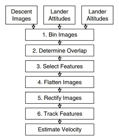
The first step reduces the image size to 256 x 256 resolution. The smaller the resolution, the faster that image processing calculations can be performed – but at the possible expense of accuracy. The second step was responsible for estimating the maximum possible area of overlap in consecutive images to minimise the search area for features (there’s no point in detecting features in regions of an image that you know are not going to be present in the second). This was done by taking into consideration knowledge from sensors of things such as the rover’s altitude and orientation. The third step picked out two features from an image using the Harris corner detector (discussed here in this OpenCV tutorial). Only one feature is needed for the algorithm to work but two were detected in case one feature could not be located in the following image. A few noise “clean-up” operations on images were performed in step 4 to reduce effects of things such as blurring.
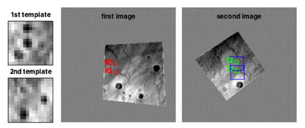
Step 5 is interesting. The feature patches (aka feature templates) and search windows in consecutive images were rectified (rotated, twisted, etc.) to remove orientation and scale differences in order to make searching for features easier. In other words, the images were rotated, twisted and enlarged/diminished to be placed on the same plane. An example of this from the actual mission (from the Spirit rover’s descent) is shown in the image below. The red squares in the first image are the detected feature patches that are shown in green in the second image with the search windows shown in blue. You can see how the first and second images have been twisted and rotated such that the feature size, for example, is the same in both images.
Step 6 was responsible for locating in the second image the two features found in the first image. Moravec’s correlator (an algorithm developed by Hans Moravec and published in his PhD thesis way back in 1980) was used for this. The general idea in this algorithm is to minimise the search area first instead of searching over every possible location in an image for a match. This is done by first selecting potential regions in an image for matches and only there is a more exhaustive search performed.
The final step is combining all this information to calculate the velocity vector. In total, the DIMES algorithm took 14 seconds to run up there in the atmosphere of Mars. It was run by both rovers during their descent. The Spirit rover was the only one that fired its impulse rockets as a result of calculations from DIMES. Its horizontal velocity was at one stage reduced from 23.5 m/s (deemed to be slightly over a safe limit) to 11 m/s, which ensured a safe landing. Computer vision to the rescue! Opportunity’s horizontal speed was never calculated to be too fast so firing its stabilising rockets was considered to be unnecessary. It also had a successful landing.
All the above steps were performed autonomously on Mars without any human intervention.
2. Stereo Vision for Navigation
To give the MER rovers as much autonomy as possible, NASA scientists developed a stereo-vision-based obstacle detection and navigation system. The idea behind it was to give the scientists the ability to simply provide the rovers each day with a destination and for the vehicles to work things out on their own with respect to navigation to this target (e.g. to avoid large rocks).
And their system performed beautifully.
The algorithm worked by extracting disparity (depth) maps from stereo images – as I’ve already mentioned, see this OpenCV tutorial for more information on this technique. What was done, however, by the rovers was slightly different to that tutorial (for example a simpler feature matching algorithm was employed), but the gist of it was the same: feature point detection and matching was performed to find the relationship between images and knowledge of camera properties such as focal lengths and baseline distances allowed for the derivation of depth for all pixels in an image. An example of depth maps calculated in this way by the Spirit rover is shown below:

Interestingly, the Opportunity rover, because it landed on a smoothly-surfaced plain, was forced to use its navcams (that were mounted on a mast) for its navigation. Looking down from a higher angle meant that detailed texture from the sand could be used for feature detection and matching. Its hazcams returned only the smooth surface of the sand. Smooth surfaces are not agreeable to feature detection (because, for example, they don’t have corners or edges). The Spirit rover, on the other hand, because it landed in a crater full of rocks, could use its hazcams for stereoscopic navigation.
3. Visual Odometry
Finally, computer vision on Mars was used at certain times to estimate the rovers’ position and travelling distance. No GPS is available on Mars (yet) and standard means of estimating distance travelled such as counting the number of wheel rotations was deemed during desert testing on Earth to be vulnerable to significant error due to one thing: wheel slippage. So, NASA scientists decided to employ motion estimation via computer vision instead.
Motion estimation was performed using feature tracking in 3D across successive shots taken by the navcams. To obtain 3D information, once again depth maps were extracted from stereoscopic images. Distances to features could easily be calculated from these and then the rovers’ poses were estimated. On average, 80 features were tracked per frame and a photo was taken for visual odometry calculations every 75 cm (30 inches) of travel.
Using computer vision to assist in motion estimation proved to be a wise decision because wheel slippage was quite severe on Mars. In fact, at one time the rover got stuck in sand and the wheels rotated in place for the equivalent of 50m (164 feet) of driving distance. Without computer vision the rovers’ estimated positions would have been severely inaccurate.
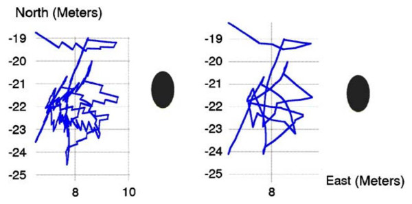
There was another instance where this was strikingly the case. At one time the Opportunity rover was operating on a 17-20 degree slope in a crater and was attempting to maneuver around a large rock. It had been trying to escape the rock for several days and had slid down the crater many times in the process. The image below shows the rover’s estimated trajectory (from a top-down view) using just wheel odometry (left), and the rover’s corrected trajectory (right) as assisted by computer vision calculations. The large rock is represented by the black ellipse. The corrected trajectory proved to be the more accurate estimation.
Summary
In this post I presented the three ways computer vision was used by the Spirit and Opportunity rovers during their MER missions on Mars. These three ways were:
- Estimating horizontal speeds during their descent onto the Red Planet to ensure the rovers had a smooth landing.
- Extracting 3D information of its surroundings using stereoscopic imagery to assist in navigation and obstacle detection.
- Using stereoscopic imagery once again but this time to provide motion and pose estimation on difficult terrain.
In this way, computer vision gave the rovers a significant amount of autonomy (much, much more autonomy than its predecessor, the Sojourner rover) that ultimately gave the rovers a safe landing and allowed the robots to traverse up to 370 m (1213 feet) per day. In fact, the Opportunity rover is still active on Mars now. This means that the computer vision techniques described in this post are churning away as we speak. If that isn’t neat, I don’t know what is!
To be informed when new content like this is posted, subscribe to the mailing list (or subscribe to my YouTube channel!):

One Reply to “Computer Vision on Mars from the 2004 Exploration Rovers”